
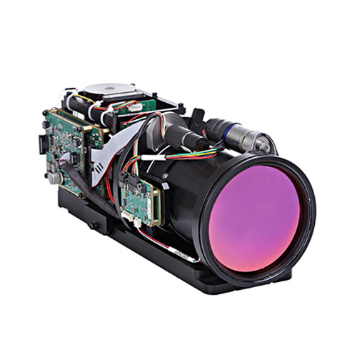
Overview
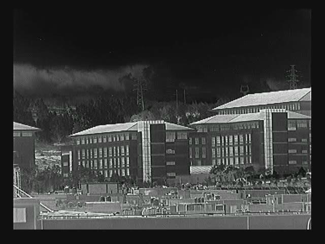
15-300mm F4 Thermal Imaging System Specification is an advanced MWIR cooled thermal imaging used for long-distance detection.The highly sensitive MWIR cooled core with 640x512 resolution can produce very clear image with very high resolution; the 15mm~300mm continuous zoom infrared lens used in the product can effectively distinguish targets such as people, vehicles and ships in long distance.
1 Technical Specification
1.1 Detector
Detector MCT 640 ×512
Spectral range 3.7 ~4.8μm
Pixel pitch 15μm
Cooling method Stirling Refrigerator
1.2 Lens
Focal length 15 ㎜~300 ㎜ continuous zoom
F 4
1.3 Performance
FOV range 1.83°(H) ×1.46°(V)to 36.5°(H) ×29.2°(V)
Cooling time ≤8 minutes in normal temperature
Video Output standard PAL format analog video signal
Frame Frequency 50Hz
NETD ≤25mk@25℃
Power source DC 24 ~32 V, with power reverse polarity
protection
Power consumption ≤15W@25℃, steady state
≤30W@25℃, start-up peak
Operation Temperature -30℃~55℃
Storage Temperature -40℃~70℃
1.4 Command and Control
Control communication RS232
Correction manual correction/background correction
Polarity control white hot/black hot switch
Electronic Zoom ×2/×4 electronic zoom
Image enhancement Yes
Cross display Yes
Image turning Horizontal/vertical
2 Physical Parameters
Weight ≤2200g
Sizes see below
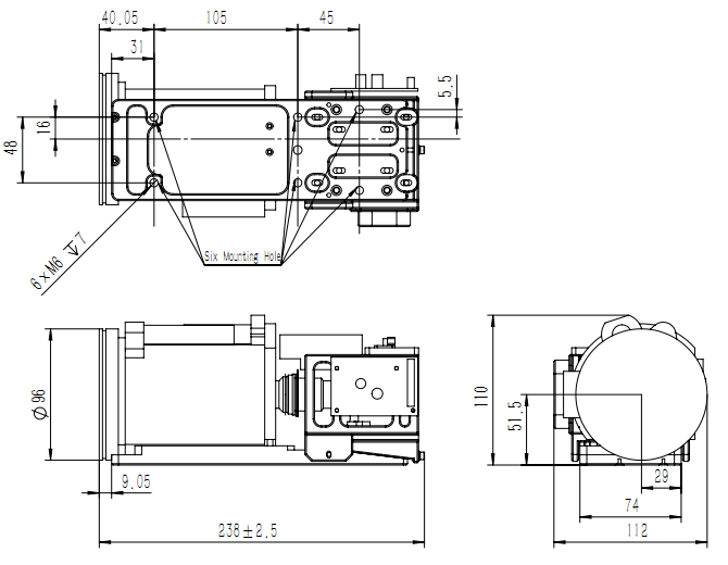
Figure2. Mechanical size illustration
3 Core Electrical Interface Definition
Table 1. Connector (HARWIN:M80-5401605) pin definitions
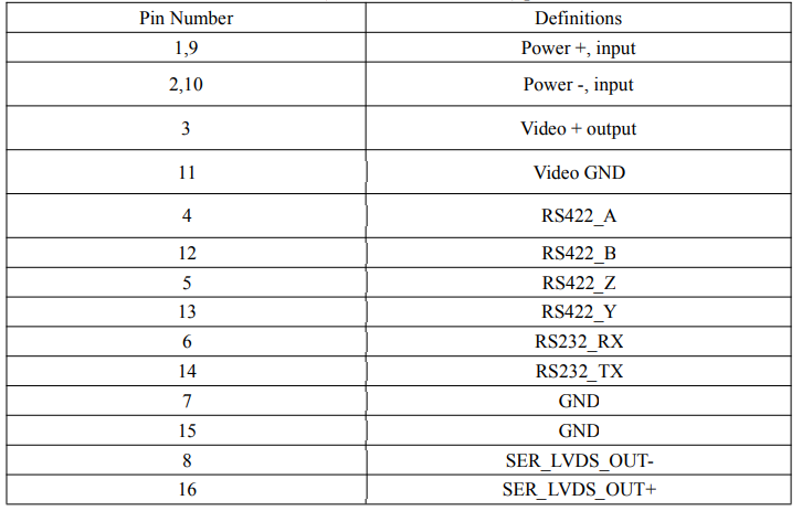
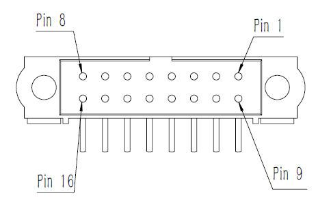
Figure3. M80-5401605 pin sequence diagram
4 Communication protocol
4.1 Electrical Interface Description for Communication
Channel
Communication between the thermal infrared imager and the host is achieved via an RS232 asynchronous serial communication interface,whose serial port setting is as follows:
Baud rate: 19200 bps
Start bits 1 bit
Stop bits: 1 bit
Verification: None
Data bits: 8 bit
The parameters listed above may be different in practice, subject to requirement of the client.
4.2 Software Interface Description for Communication
Protocol
a) The host controls the certain action of the thermal infrared imager by sending commands to the thermal infrared imager through the serial port; communication command is sent in given packet format; if the interval between characters of the packet sent from the host to the thermal infrared imager is over 10ms, the imaging system may decline to implement the command.
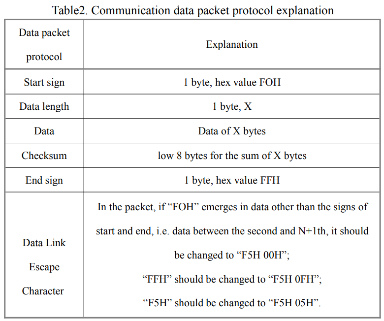
b) Packet Protocol
Packet protocol is defined in Figure 4: Packet Protocol.
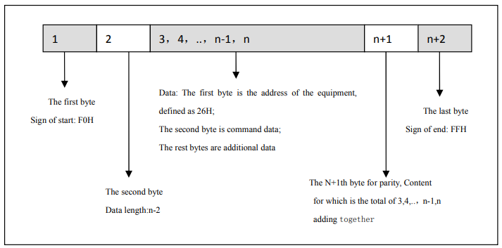
Figure4 Packet Protocol
4.3 Communication Protocol Control Commands List
Communication protocol control commands list—pool of commands that can be sent from the host. See Table 3.
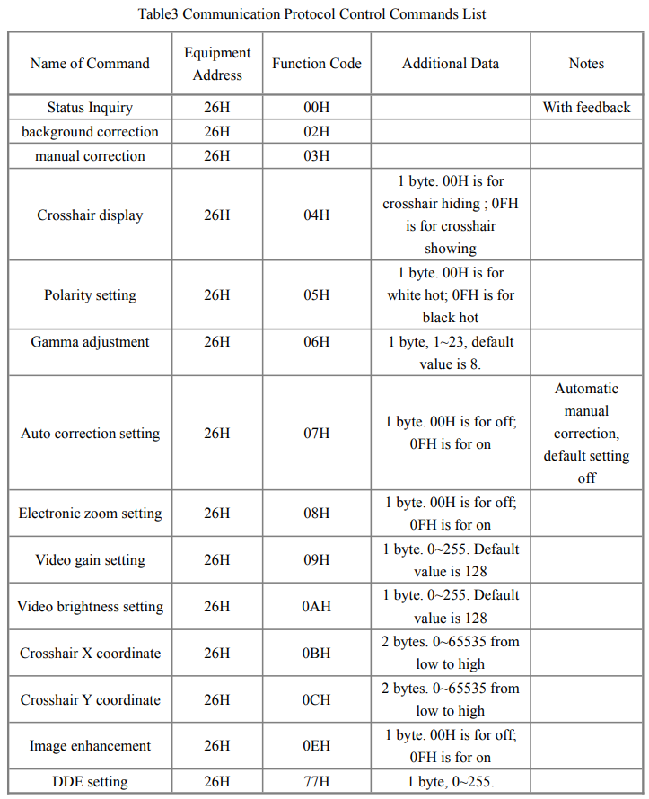
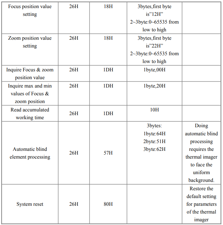
The commands listed above may be different in practice, subject to requirement of the client. The set ID is 26H, but it can be changed according to application environment.
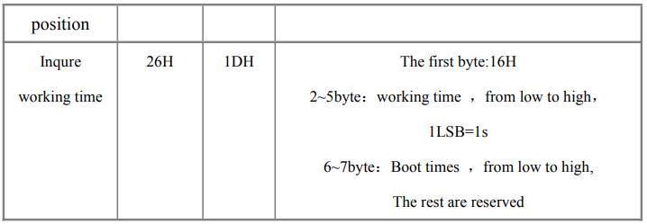
4.4 Communication Protocol Feedback Commands List
Communication protocol feedback commands list – pool of the thermal infrared
imager feedback commands.
Instead of actively sending data, the thermal infrared imager only responds when it receives “status inquiry” command. Its responding packet conforms to“communication packet protocol”
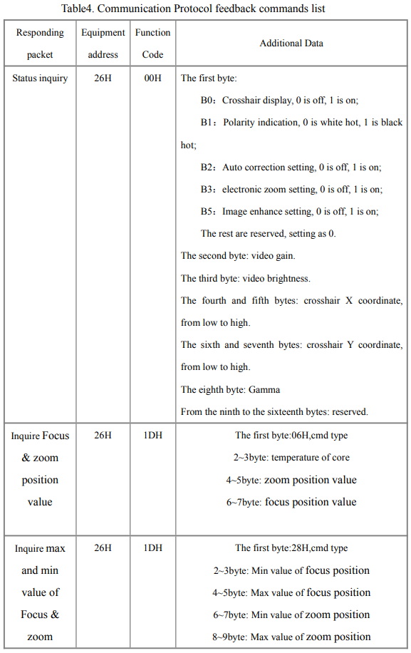
The commands listed above may be different in practice, subject to requirement of the client. The set ID is 26H, but it can be changed according to application environment.
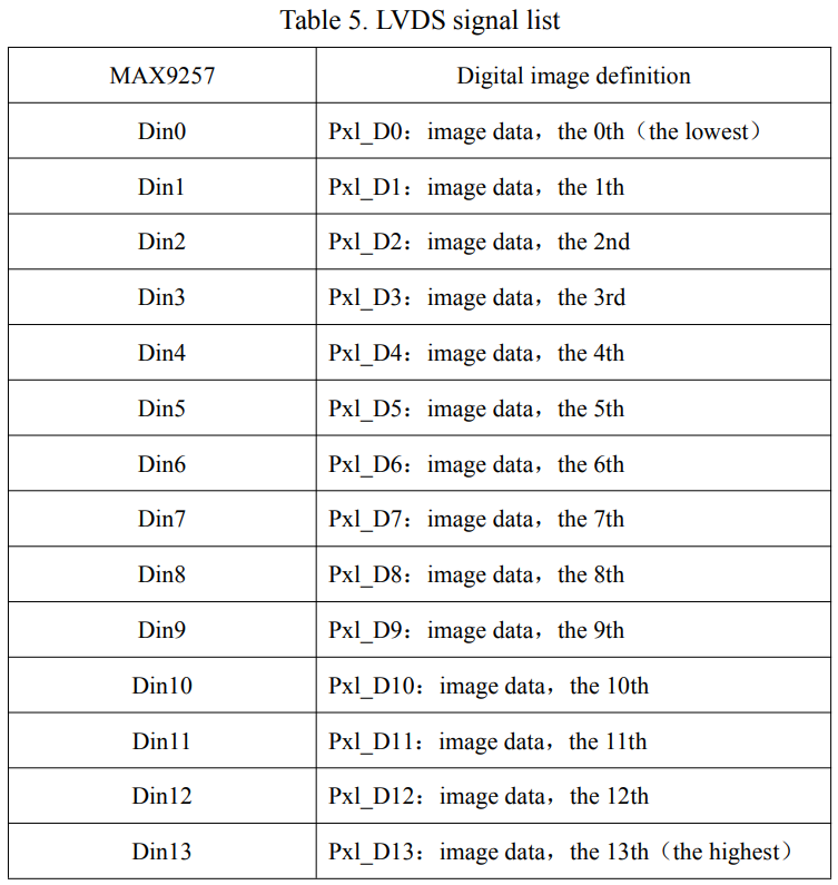
5 Digital video interfaces
LVDS transmission chip MAX9257 (use MAX9258 to receive). Definitions are in Table 5.
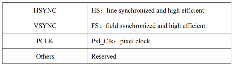
Data time sequence which is transmitted to MAX9257 transmission chip is showed in the following figure.

Figure 5. Data time sequence transmitted to MAX9257 transmission chip