


Overview
1 Introduction
Fiber Optic Gyroscope, as a new type of full solid GYROSCOPE, has the advantages of starting fast, wide measurement, and high reliability. The F2X70 type is a dual-axis accuracy Fiber Optic Gyroscope instrument can be applied in the field of vehicle stability platforms, guides, and hanging warehouses.
1.1 Application range
The instructions are only suitable for F2X70 products, including performance indicators, technical conditions, shape size and installation and use. Among them, the technical conditions include the environmental range, electrical performance, and physical characteristics of the product.
1.2 Main parameters
1.2.1 Fiber Optic Gyroscope instrument Main performance indicators:
Table 1 The main performance indicator of the product
|
Zero Drift stability |
≤0.20 °/hr (1σ, 10s) |
2h continuous test, 10ssmoothing results |
|
stable schedule |
<100s |
|
|
Zero Drift repeatability |
≤0.2 °/hr (1S) |
3 Test data calculation results |
|
Resolution |
≤0.2 °/hr (1S) |
|
|
Random Walk coefficient |
≤0.02°/ |
|
|
FULL TEMPZERO DRIITPEPEATABILITY |
≤ 0.5 °/hr |
|
|
Scale Factor Non linearity |
≤20 PPM (1S) |
Room temperature |
|
Scale Factor repeatability |
≤50 PPM (1S) |
Room temperature |
|
dynamic range |
± 400 °/s |
|
|
Bandwidth |
≥500 Hz |
|
|
Operating temperature |
-40℃~+65℃ |
|
|
Storage temperature |
-50℃~+70℃ |
|
|
Vibration condition |
4.2G, 20Hz ~ 2000Hz |
|

1.2.2 mechanics test
1.2.2.1 Sine scan vibration
GYROSCOPE is fixed on the vibration platform in the direction of vibration. Gyroscope is scanned in three directions, corresponding to the X -axis, Y axis, and Z axis. Vibration steps; vibration platform adds excitement, power the Gyroscope, and test the GYROSCOPE output value after a certain period of time (Gyroscope startup time), about 5 minutes; sine vibration. Vibration conditions: 20Hz-20000Hz, scanning time 5min, amplitude of 4.2g. During the vibration process, the Gyroscope output is recorded.
Random vibration
Vibration frequency: 20Hz ~ 2000Hz
Vibration time: each axis is 5min respectively
Vibration direction: X, Y, Z axis
Vibration spectrum: see Figure 1

Attachment 1 vibration spectrum
Index requirements:
Fiber Optic Gyroscope has no resonance in the range of 20Hz to 2000Hz.
Random vibration: Zero Drift value and front and rear Zero Drift average absolute value requirements are less than 0.3º/h.
1.2.2.2 Mechanical impact according to the requirements of Table 2.
Table 2 impact test condition
|
Peak acceleration (G) |
30 |
|
Duration (MS) |
10 |
|
Number of shocks |
3 times per direction |
|
Waveform |
Semi -sine wave |
|
direction |
X, y, z |
|
|
Note: The interval between two shocks is not less than 1.5s |
During the impact process, the product is in a state of power. When the mechanical impact product is completed, it should be able to work normally. The zero change value before and after the impact is less than 0.3º/h.
2 communication protocol
2.1 Fiber Optic Gyroscope communication protocol
2.1 RS-422 method
a) Potter rate: 460.8K;
b) Data refresh rate: 2000Hz
c) Communication frame format
Each frame contains 9 bytes, the first byte is A5, and the second, third, and four -bytes are the high, middle and low data of GYROSCOPE in the horizontal direction. The 11th bit of the eighth byte is count, the counting range is 0 to 255, and the ninth byte is the sum of the first to eighth byte, and the low is 8 bits.
See Table 2 in the format, 11 digits per byte, and the order is: Starting position 1
8 digits of data bits (first sends low and then high), 1 bit of Qi school test, stop digit 1 bit
d) Communication rules
Gyroscope uses broadcast -type hair numbers
Table 3 Output Data Frame Each byte format
|
Number of bytes |
significance |
7 |
6 |
5th |
4 |
3rd |
Position 2 |
1 |
0 |
|
1 |
Frame head |
1 |
0 |
1 |
0 |
0 |
1 |
0 |
1 |
|
2 |
Ping GYROSCOPE high 8 -bit |
PD23 |
PD22 |
PD21 |
PD20 |
PD19 |
PD18 |
PD17 |
PD16 |
|
3 |
8 -bit in Gyroscope |
PD15 |
PD14 |
PD13 |
PD12 |
Pd11 |
PD10 |
PD9 |
PD8 |
|
4 |
Ping GYROSCOPE low 8 -bit |
PD7 |
PD6 |
PD5 |
PD4 |
PD3 |
PD2 |
PD1 |
PD0 |
|
5 |
Gyroscope high 8 -bit |
CD23 |
CD22 |
CD21 |
CD20 |
CD19 |
CD18 |
CD17 |
CD16 |
|
6 |
8 -bit in gyroscope |
CD15 |
CD14 |
CD13 |
CD12 |
CD11 |
CD10 |
CD9 |
CD8 |
|
7 |
Dagging Gyroscope low 8 -bit |
CD7 |
CD6 |
CD5 |
CD4 |
CD3 |
CD2 |
CD1 |
CD0 |
|
8 |
count |
C7 |
C6 |
C5 |
C4 |
C3 |
C2 |
C1 |
C0 |
|
9 |
Frame verification |
1 to 8 bytes and low 8 -bit |
|||||||
3 Wiring definition
Gyroscope electrical interface uses the J30-15ZK connector. The node definition is shown in Table 4.
|
Order number |
Connection definition |
Standard |
color |
|
1 |
Serial port T+ |
Tx+ |
yellow |
|
2 |
Serial port T- |
Tx- |
Orange |
|
3 |
Serial R+ |
Rx+ |
blue |
|
4 |
Serial R- |
Rx- |
green |
|
5、13 |
PSU+5V |
+5V |
red |
|
6、7 |
PSU |
GND |
black |
4 shape size map
Horizontal dual -axis Fiber Optic Gyroscope instrument Dimensions: 70mm × 70mm × 43mm, installation size: four -hole 62mm × 62 mm, installation screw: 4 M3 screws, the shape and installation size are shown in Figure 2.
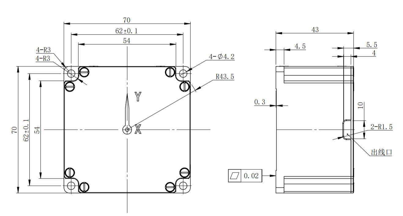
Figure 2 F2X70 Type shape size diagram