

Overview
1 Introduction
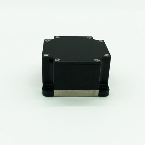
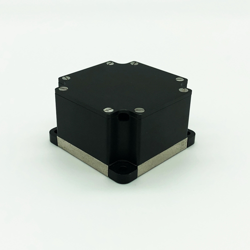
The fiber optic gyroscope, as a new type of all-solid-state gyroscope, has the advantages of fast start-up, wide measuring range and high reliability. F60M single-axis medium-high precision fiber optic gyroscope can be applied to the application requirements of medium-high precision inertial guidance systems such as land-based positioning and orientation, vehicle-mounted north finder, airborne heading and marine gyroscope compass.
1.1 Application scope
This manual is only applicable to F60M type products, including performance indicators, technical conditions, external dimensions and installation and use. Among them, the technical conditions include the environmental range, electrical performance, and physical characteristics of the product.
1.2 Main parameters
1.2.1 fiber optic gyroscope instrument main performance indicators.
Table 1 Main performance indicators of the product
|
zero stability |
≤0.20°/hr(1σ,10s) |
2 h continuous test, 10 s smoothing results |
|
zero drift repeatability |
≤0.20°/hr(1σ) |
6 times test data calculation results |
|
full temp zero drift repeatability |
≤0.3°/hr |
-40℃~+60℃ |
|
full temp zero stability |
≤0.30°/hr(1σ,10s) |
-40℃~+60℃ |
|
random walk coefficient |
≤0.01°/ |
|
|
scale factor non-linearity degree |
≤50 ppm(1σ) |
room temperature |
|
scale factor repeatability |
≤50 ppm(1σ) |
room temperature |
|
full temp scale factor repeatability |
≤600 ppm(1σ) |
-40℃~+60℃ |
|
dynamic range |
±400°/s |
|
|
Operating temperature |
-40℃~+70℃ |
|
|
Storage temperature |
-50℃~+70℃ |
|
|
Vibration conditions |
4.2 g,20 Hz~2000 Hz |
Sweeping frequency vibration without resonance |

1.2.2 Mechanical test
1.2.2.1 Sine sweep vibration
The gyroscope is fixed on the shaking table by the tooling according to the vibration direction. The gyroscope is subjected to sinusoidal scanning in 3 directions, corresponding to the X-axis, Y-axis and Z-axis directions. Vibration steps; shaking table with excitation, powering up the gyroscope, after warming up for a certain time (gyroscope start-up time), testing the gyroscope output value, about 5 min; sine vibration. Vibration conditions: 20 Hz-2000 Hz , scan time 5min, amplitude 4.2 g. During vibration, gyroscope output is recorded.
Random vibration
Vibration frequency: 20 Hz~2000 Hz
Vibration time: 5 min for each axis respectively
Vibration direction: X, Y, Z axis
Vibration spectrum: see the attached Figure 1

Attachment Figure 1 vibration spectrum
Requirements
fiber optic gyroscope in the range of 20 HZ ~ 2000 Hz sine sweep scan without resonance.
Random vibration: the absolute value of zero drift value in vibration and the average value of zero drift before and after is required to be less than 0.5 º/h.
1.2.2.2 Mechanical shock according to the requirements of Table 2.
Table 2 impact test conditions
|
Peak acceleration (g) |
30 |
|
Duration (ms) |
10 |
|
Number of shocks |
3 times in each direction |
|
Waveform |
Half sine wave |
|
Direction |
X, Y, Z |
|
|
Note: The interval between two shocks is not less than 1.5 s |
During the impact process, the product is in the energized state, complete mechanical impact products, should be able to work normally, the zero change value before and after the impact is less than 0.3 º / h.
2 Communication protocol
2.1 fiber optic gyroscope communication protocol
2、 Communication protocol
2.1 RS-422 mode (bidirectional)
1) Bi-directional serial communication, conforming to the RS-422 interface standard.
2) gyroscope valid data is 32 bits.
3) valid data for temperature is 14 bits.
4) Data transmission baud rate of 460.8 kbps.
5) Data format.
a) Data transmission format: 11 bits per frame, including: the first bit is the start bit (0), the second to the ninth bit is the data bit, the tenth bit is the even parity bit, and the eleventh bit is the stop bit.
b) Calibration mode: even calibration.
c) The valid data of gyroscope is 32 bits (the highest bit is the sign bit, 0 is "+", 1 is "-"), and the valid data of temperature is 14 bits (the highest bit is the sign bit, 0 is "+", 1 is "-").
d) Packet format: each transmission includes 10 bytes, the first byte is the frame header (80H); the second byte is the first byte of gyroscope data (low byte); the third byte is the second byte of gyroscope data; the fourth byte of gyroscope data; the fifth byte is the fourth byte of gyroscope data; the sixth byte is gyroscope fifth byte data (high byte); the seventh byte is the check bit, which is the XOR value of the first five bytes (gyroscope data) in the data packet; the eighth byte is the low byte of temperature data; the ninth byte is the high byte of temperature data; the tenth bit is the check bit, which is the XOR value of the first eight bytes (gyroscope data) in the data packet.
e) Data storage method.
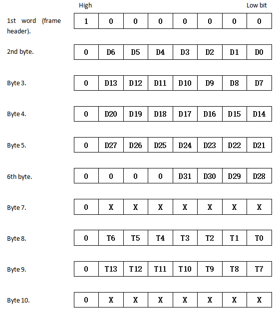
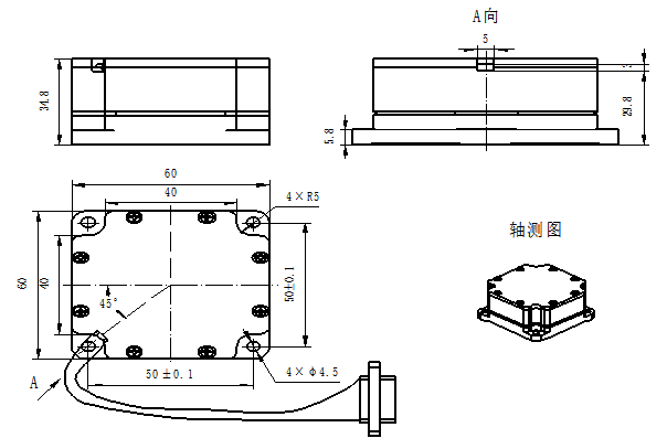
Fig. 2 Dimensional drawing of F60M type
The fiber optic gyroscope instrument leads externally to the J30J-9ZKP socket, and the definition of the contact point is shown in Table 1.
Table 1 gyroscope output socket electrical characteristics
|
J30J-9ZKP |
Definition |
Remarks |
|
1 |
PSU+5V |
Main board power supply PSU |
|
2 |
GND |
|
|
3 |
PSU-5V |
|
|
4 |
VI (+5V) |
Light source board power supply |
|
5 |
GND (ground) |
|
|
6 |
T+ |
gyroscope sends 422T+ |
|
7 |
T- |
gyroscope sends 422T- |
|
8 |
R+ |
gyroscope sends 422R+ |
|
9 |
R- |
gyroscope sends 422R- |