
Overview
1 Introduction
fiber optic gyroscope as a new type of all-solid-state gyroscope, has the advantages of fast start-up, wide measurement range and high reliability. F2X64 model is a two-axis low precision fiber optic gyroscope instrument can be applied to vehicle stabilization platform, guide head, crane bin and other fields.
1.1 Application scope
This manual is only applicable to F2X64 type product, which contains the performance index, technical conditions, external dimensions and installation and use. Among them, the technical conditions include the environmental range, electrical performance, and physical characteristics of the product.
1.2 Main parameters
1.2.1 fiber optic gyroscope instrument main performance indicators.
Table 1 Main performance indicators of the product
|
zero stability |
≤0.5°/hr(1σ,10s) |
≤1.0°/hr(1σ,10s) |
2h continuous test, 10ssmoothing results |
|
Stability time |
<10s |
<10s |
|
|
zero drift repeatability |
≤0.5°/hr(1σ) |
≤1.0°/hr(1σ) |
Calculated results from 3 tests |
|
full temp zero drift repeatability |
≤0.5°/hr |
≤1.0°/hr |
|
|
scale factor non-linearity degree |
≤30 ppm(1σ) |
≤50 ppm(1σ) |
room temperature |
|
scale factor repeatability |
≤50 ppm(1σ) |
≤100 ppm(1σ) |
ambient temperature |
|
dynamic range |
±400°/s |
|
|
|
Bandwidth |
≥100 Hz |
|
|
|
Operating temperature |
-40℃~+65℃ |
|
|
|
Storage temperature |
-50℃~+70℃ |
|
|
|
Vibration condition |
4.2g,20Hz~2000Hz |
|
|
1.2.2 Mechanical test
1.2.2.1 Sine scan vibration
The gyroscope is fixed on the shaking table by the tooling according to the vibration direction. The gyroscope is subjected to sinusoidal scanning in 3 directions, corresponding to the X-axis, Y-axis and Z-axis directions. Vibration steps; shaking table with excitation, powering up the gyroscope, after warming up for a certain time (gyroscope start-up time), testing the gyroscope output value, about 5min; sine vibration. Vibration conditions: 20Hz-2000Hz , scan time 5min, amplitude 4.2g. During vibration, gyroscope output is recorded.
Random vibration
Vibration frequency: 20Hz~2000Hz
Vibration time: 5min for each axis respectively
Vibration direction: X, Y, Z axis
Vibration spectrum: see the attached Figure 1

Attachment Figure 1 vibration spectrum
Requirements
fiber optic gyroscope in the range of 20HZ ~ 2000Hz sine sweep scan without resonance.
Random vibration: the absolute value of zero drift value in vibration and the average value of zero drift before and after is required to be less than 1º/h.
1.2.2.2 Mechanical shock according to the requirements of Table 2.
Table 2 impact test conditions
|
Peak acceleration (g) |
30 |
|
Duration (ms) |
10 |
|
Number of shocks |
3 times in each direction |
|
Waveform |
Half sine wave |
|
Direction |
X, Y, Z |
|
|
Note: The interval between two shocks is not less than 1.5s |
During the impact process, the product is in the energized state, complete the mechanical impact product, should be able to work normally, the zero change value before and after the impact is less than 1º / h.
2 Communication protocol
2.1 fiber optic gyroscope communication protocol
2.1 RS-422 mode
a) Baud rate: 921600bps.
b) Data refresh rate: 500Hz
c) Communication frame format
Each frame contains 8 bytes, the first byte is A5, the second, third and fourth bytes are the high and low octet data of gyroscope in horizontal direction, the fifth, sixth and seventh bytes are the high and low octet data in vertical direction, and the eighth byte is the result of the second to seventh bytes corresponding to each bit of heterodyne.
The format is shown in Table 2, with 11 bits per byte, in the following order Start bit 1 bit
Data bit 8 bits (send low first, then high), odd parity bit 1 bit, stop bit 1 bit
d) Communication rules
The gyroscope uses the broadcast type to send the numbers
Table 3 Format of the output data frame bytes
|
Number of bytes |
Meaning |
Bit 7 |
Bit 6 |
Bit 5 |
Bit 4 |
Bit 3 |
Bit 2 |
Bit 1 |
Bit 0 |
|
1 |
Frame header |
1 |
0 |
1 |
0 |
0 |
1 |
0 |
1 |
|
2 |
Flat gyroscope high 8 bits |
PD23 |
PD22 |
PD21 |
PD20 |
PD19 |
PD18 |
PD17 |
PD16 |
|
3 |
8 bits in flat gyroscope |
PD15 |
PD14 |
PD13 |
PD12 |
PD11 |
PD10 |
PD9 |
PD8 |
|
4 |
Flat gyroscope lower 8 bits |
PD7 |
PD6 |
PD5 |
PD4 |
PD3 |
PD2 |
PD1 |
PD0 |
|
5 |
Pendant gyroscope high 8 bits |
CD23 |
CD22 |
CD21 |
CD20 |
CD19 |
CD18 |
CD17 |
CD16 |
|
6 |
8 bits in pendant gyroscope |
CD15 |
CD14 |
CD13 |
CD12 |
CD11 |
CD10 |
CD9 |
CD8 |
|
7 |
Pendant gyroscope lower 8 bits |
CD7 |
CD6 |
CD5 |
CD4 |
CD3 |
CD2 |
CD1 |
CD0 |
|
8 |
Frame checksum |
Byte 2 to 7 isochronous by bit |
|||||||
3 Wiring Definition
The gyroscope electrical interface uses the J30-15ZK connector, see Table 4 for node definitions.
|
Contact number |
Node definition |
Marking |
Color |
|
1 |
Serial port T+ |
TX+ |
Yellow |
|
2 |
Serial T- |
TX- |
Orange |
|
3 |
Serial R+ |
RX+ |
Blue |
|
4 |
Serial R- |
RX- |
Green |
|
5、13 |
PSU+5V |
+5V |
Red |
|
6、7 |
PSU ground |
GND |
Black |
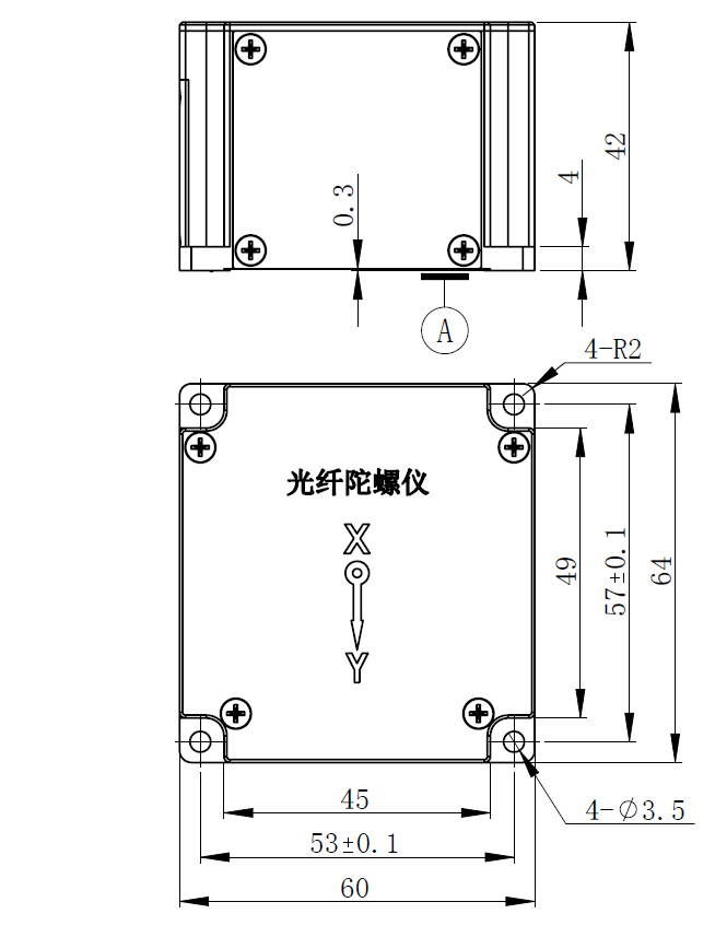
4 External dimension drawing
Horizontal dual-axis fiber optic gyroscope instrument form factor: 64mm × 60mm × 42mm, mounting size: four holes 53mm × 57 mm, mounting screws: four M3 screws, the shape and mounting dimensions are shown in Figure 2.