
Overview
1 Introduction
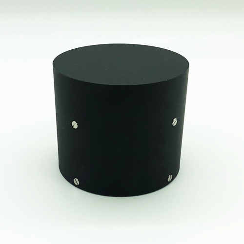
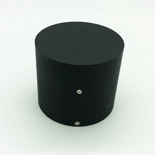
Fiber optic inertial measurement unit is an inertial product developed for navigation and guidance, attitude measurement and control of small missiles and guided bombs, which is composed of three all-solid-state fiber optic gyroscope instruments, three quartz accelerometers and data packing board, etc. It measures the angular velocity and linear acceleration of carrier movement, and provides information for carrier attitude and navigation control. The measurement results are output via RS422 serial port.
1.1 Application scope
This manual is only applicable to F3X80-IMU type products, and contains performance indexes, technical conditions, external dimensions and installation and use. Among them, the technical conditions include the environmental range, electrical performance, and physical characteristics of the product.
1.2.1 Main performance indicators of fiber optic gyroscope instrument.
Table 1 The main performance indicators of the product
|
fiber optic gyroscope instrument main performance indicators |
Main index parameters |
F3X80MI |
F3X80LI |
|
|
M type |
L type |
|
|
Room temperature zero drift repeatability(period by period, day by day)( º/ h) |
≤0.3 |
≤0.5 |
|
|
Zero stability at fixed temperature( º/ h) |
≤0.3 |
≤0.5 |
|
|
Room temperature scale factor repeatability ( ppm) |
≤30 |
≤30 |
|
|
Scale factor asymmetry at constant temperature (ppm) |
≤30 |
≤30 |
|
|
Scale factor non-linearity at constant temperature (ppm) |
≤30 |
50 |
|
|
Threshold value (º/ h) |
≤0.5º/ h |
||
|
Angular rate range( º/s) |
-500~+500 º/s |
||
|
Bandwidth (Hz) |
100 |
||
|
Dimension (mm) |
Ф80*70 |
||
|
Weight (g) |
780±20 (including accelerometer) |
||
|
Operating temperature (℃) |
-40~+65 |
||
Quartz accelerometer parameters
|
Serial number |
Item |
Technical regulations |
|
1 |
Range (g) |
≥±40 |
|
2 |
scale factor temperature coefficient(ppm /℃) |
≤100 |
|
3 |
scale factor monthly stability(ppm) |
≤100 |
|
4 |
Bias value (mg) |
≤±7 |
|
5 |
bias temperature factor (μg /℃) |
≤100 |
|
6 |
Bias monthly stability (μg) |
≤100 |
|
7 |
Second-order non-linearity factor (μg /g2) |
≤20 |
|
8 |
Mounting angle (") |
≤200 |
|
9 |
Appearance |
No scratches, cracks, rusts |
|
10 |
Insulation |
≥20MΩ; (100V),25℃±5℃, humidity≤80% |
1.2.2 Mechanical test
1.2.2.1 Sine scan vibration
The gyroscope is fixed on the shaking table by the tooling according to the vibration direction, and the gyroscope is scanned sinusoidal in 3 directions, corresponding to the X-axis, Y-axis and Z-axis directions. Vibration steps; shaking table with excitation, powering up the gyroscope, after warming up for a certain time (gyroscope start-up time), testing the gyroscope output value, about 5min; sine vibration. Vibration conditions: 20Hz-2000Hz , scan time 5min, amplitude 4.2g. During vibration, gyroscope output is recorded.
Random vibration
Vibration frequency: 20Hz~2000Hz
Vibration time: 5min for each axis respectively
Vibration direction: X, Y, Z axis
Vibration spectrum: see the attached Figure 1

Attachment Figure 1 vibration spectrum
Requirements
fiber optic gyroscope in the range of 20HZ ~ 2000Hz sine sweep scan without resonance.
Random vibration: the absolute value of zero drift value in vibration and the average value of zero drift before and after is required to be less than 1º/h.
1.2.2.2 Mechanical shock according to the requirements of Table 2.
Table 2 impact test conditions
|
Peak acceleration (g) |
30 |
|
Duration (ms) |
10 |
|
Number of shocks |
3 times in each direction |
|
Waveform |
Half sine wave |
|
Direction |
X, Y, Z |
|
|
Note: The interval between two shocks is not less than 1.5s |
During the impact, the product is in an energized state, complete mechanical impact products, should be able to work normally, the zero change value before and after the impact is less than 1º / h.
2.1 IMU data sending protocol
Annex A.
Baud rate: 460800, no parity bit, 1 stop bit
Transmission frequency: 400Hz
Sending data protocol.
|
Byte |
Name |
Unit |
Value |
Conversion |
Type |
|
0 |
Frame header byte 1 |
|
0xAA |
|
uchar |
|
1 |
Frame header byte 2 |
|
0xAA |
|
uchar |
|
2 |
Data transmission count |
|
1~200 |
|
uchar |
|
3 |
Self-test byte |
|
255 |
|
uchar |
|
4~7 |
X-axis gyroscope |
|
32bit low bit before high bit after |
|
signed int32 |
|
8~11 |
Y-axis gyroscope |
|
32bit low in front and high in back |
|
signed int32 |
|
12~15 |
Z-axis gyroscope |
|
32bit low in front and high in back |
|
signed int32 |
|
16~19 |
X-axis accelerometer |
|
32bit low in front and high in back |
|
signed int32 |
|
20~23 |
Y-axis accelerometer |
|
32bit low in front and high in back |
|
signed int32 |
|
24~27 |
Z-axis accelerometer |
|
32bit low in front and high in back |
|
signed int32 |
|
28,29 |
X-axis gyroscope temperature |
|
16bit low bit before high bit after |
1/16 |
signed int16 |
|
30,31 |
Y-axis gyroscope temperature |
|
16bit low bit before high bit after |
1/16 |
signed int16 |
|
32,33 |
Z-axis gyroscope temperature |
|
16bit low bit before high bit after |
1/16 |
signed int16 |
|
34,35 |
X-axis accelerometer temperature |
|
16bit low bit before high bit after |
1/16 |
signed int16 |
|
36,37 |
Y-axis accelerometer temperature |
|
16bit low in front and high in back |
1/16 |
signed int16 |
|
38,39 |
Z-axis accelerometer temperature |
|
16bit low in front and high in back |
1/16 |
signed int16 |
|
40 |
Checksum |
|
4~39 byte iso-or sum |
|
uchar |
|
41 |
End of frame |
|
0xBB |
|
uchar |
Annex B
a) RS422, baud rate: 921600bps.
b) Data output frequency: 4000Hz.
c) Data format: 1 start bit, 8 data bits, 1 even parity bit, 1 stop bit.
d) The first byte of frame header is 0x80, the second byte to the fourth byte is X gyroscope data, the fifth byte to the seventh byte is Y gyroscope data, the eighth byte to the tenth byte is Z gyroscope data; the eleventh byte is frame checksum.
|
Serial number |
Meaning |
Data type |
Length |
Value |
|
1 |
Packet header |
Unsigned integer |
1 byte |
0x80 |
|
2~4 |
X gyroscope data |
Signed integer |
3 bytes |
1LSB=4.8e-5degrees/sec,unit: degrees/sec |
|
5~7 |
Y gyroscope data |
Signed integer |
3 bytes |
1LSB=4.8e-5degrees/sec,unit: degrees/sec |
|
8~10 |
Z gyroscope data |
Signed integer |
3 bytes |
1LSB=4.8e-5degrees/sec,unit: degrees/sec |
|
11 |
Calibration |
Unsigned integer |
1 byte |
2~10 bytes of iso-or |
e) gyroscope data in 24-bit complementary binary format, with D23 as the sign bit.
f) The frame checksum byte is an iso-or of 9 data bytes (2~10 bytes), and the data format is shown in the following table.
|
Frame header |
1 |
0 |
0 |
0 |
0 |
0 |
0 |
0 |
|
xH8 |
xD23 |
xD22 |
xD21 |
xD20 |
xD19 |
xD18 |
xD17 |
xD16 |
|
xM8 |
xD15 |
xD14 |
xD13 |
xD12 |
xD11 |
xD10 |
xD9 |
xD8 |
|
xL8 |
xD7 |
xD6 |
xD5 |
xD4 |
xD3 |
xD2 |
xD1 |
xD0 |
|
yH8 |
yD23 |
yD22 |
yD21 |
yD20 |
yD19 |
yD18 |
yD17 |
yD16 |
|
yM8 |
yD15 |
yD14 |
yD13 |
yD12 |
yD11 |
yD10 |
yD9 |
yD8 |
|
yL8 |
yD7 |
yD6 |
yD5 |
yD4 |
yD3 |
yD2 |
yD1 |
yD0 |
|
zH8 |
zD23 |
zD22 |
zD21 |
zD20 |
zD19 |
zD18 |
zD17 |
zD16 |
|
zM8 |
zD15 |
zD14 |
zD13 |
zD12 |
zD11 |
zD10 |
zD9 |
zD8 |
|
zL8 |
zD7 |
zD6 |
zD5 |
zD4 |
zD3 |
zD2 |
zD1 |
zD0 |
|
Calibration |
C7 |
C6 |
C5 |
C4 |
C3 |
C2 |
C1 |
C0 |
Annex C
a) RS422, baud rate: 921600bps.
b) Data output frequency: 4000 Hz.
c) Data format: 1 start bit, 8 data bits, 1 even parity bit, 1 stop bit.
d) The first byte of frame header is 0x80, the second byte to the fourth byte is Xaccelerometer data, the fifth byte to the seventh byte is Yaccelerometer data, the eighth byte to the tenth byte is Zaccelerometer data; the eleventh byte is frame checksum.
|
Serial number |
Meaning |
Data type |
Length |
Value |
|
1 |
Packet header |
Unsigned integer |
1 byte |
0x80 |
|
2~4 |
Xaccelerometer data |
Signed integer |
3 bytes |
|
|
5~7 |
Yaccelerometer data |
Signed integer |
3 bytes |
|
|
8~10 |
Zaccelerometer data |
Signed integer |
3 bytes |
|
|
11 |
Checksum |
Unsigned integer |
1 byte |
2 to 10 bytes of iso-or |
e) accelerometer data in 24-bit complementary binary format, with D23 as the sign bit.
f) The frame checksum byte is an iso-or of 9 data bytes (2~10 bytes), and the data format is shown in the following table.
|
Frame header |
1 |
0 |
0 |
0 |
0 |
0 |
0 |
0 |
|
xH8 |
xD23 |
xD22 |
xD21 |
xD20 |
xD19 |
xD18 |
xD17 |
xD16 |
|
xM8 |
xD15 |
xD14 |
xD13 |
xD12 |
xD11 |
xD10 |
xD9 |
xD8 |
|
xL8 |
xD7 |
xD6 |
xD5 |
xD4 |
xD3 |
xD2 |
xD1 |
xD0 |
|
yH8 |
yD23 |
yD22 |
yD21 |
yD20 |
yD19 |
yD18 |
yD17 |
yD16 |
|
yM8 |
yD15 |
yD14 |
yD13 |
yD12 |
yD11 |
yD10 |
yD9 |
yD8 |
|
yL8 |
yD7 |
yD6 |
yD5 |
yD4 |
yD3 |
yD2 |
yD1 |
yD0 |
|
zH8 |
zD23 |
zD22 |
zD21 |
zD20 |
zD19 |
zD18 |
zD17 |
zD16 |
|
zM8 |
zD15 |
zD14 |
zD13 |
zD12 |
zD11 |
zD10 |
zD9 |
zD8 |
|
zL8 |
zD7 |
zD6 |
zD5 |
zD4 |
zD3 |
zD2 |
zD1 |
zD0 |
|
Calibration |
C7 |
C6 |
C5 |
C4 |
C3 |
C2 |
C1 |
C0 |
3、Wiring definition
|
J30J-15ZK |
Definition |
Remark |
|
|
1、2 |
+5V |
gyroscope power supply |
|
|
3、4 |
±5V (ground) |
||
|
5、6 |
-5V |
||
|
7 |
+15V |
accelerometer power supply |
|
|
8 |
±15V (ground) |
||
|
9 |
-15V |
||
|
10 |
T1+ |
Transmit + |
400HZ Inertia group output |
|
11 |
T1- |
Transmit- |
|
|
12 |
T2+ |
Send+ |
4KHZ gyroscope output |
|
13 |
T2- |
Send- |
|
|
14 |
T3+ |
Send+ |
4KHZ accelerometer output |
|
15 |
T3- |
Transmitting- |
|
4、Product size
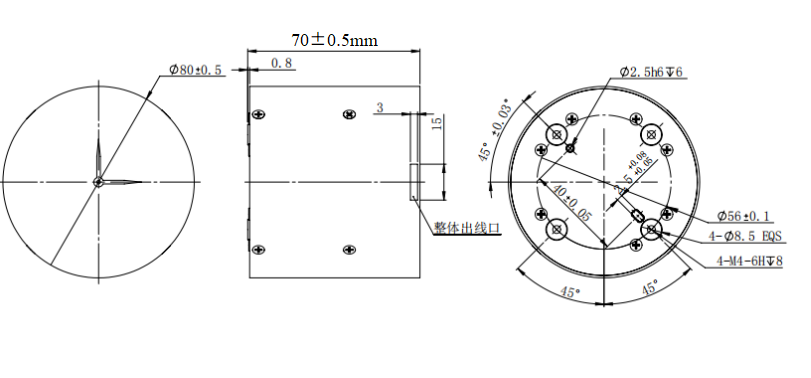
IXZ-F3X80-IMU External Dimensions