

Overview
1 Introduction
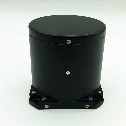
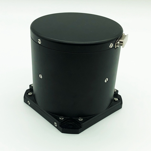
fiber optic gyroscope as a new type of all-solid-state gyroscope, has the advantages of fast start-up, wide measurement range and high reliability. Among them, F3X90-IMU type fiber optic gyroscope inertial group is designed for the needs of low and medium precision application background, using three-axis common technology, low cost and stable performance; the structure of the optical circuit, circuit integrated package, simple structure, easy installation, can be applied with small missiles, guided bombs in navigation guidance, attitude measurement and control systems.
1.1 Application Scope
This manual is only applicable to F3X90-IMU type products, and contains performance indicators, technical conditions, external dimensions and installation and use. Among them, the technical conditions include the environmental range, electrical performance, and physical characteristics of the product.
|
fiber optic gyroscope instrument main performance indicators |
Main parameters |
Main indicators |
|
|
|
H type |
M type |
|
|
Room temperature zero drift repeatability(period-by-period,day-by-day)( º/ h) |
≤0.1 |
≤0.2 |
|
|
ZERO stability at fixed temperature( º/ h) |
≤0.1 |
≤0.2 |
|
|
Room temperature scale factor repeatability ( ppm) |
≤20 |
≤50 |
|
|
Scale factor asymmetry at constant temperature (ppm) |
≤20 |
≤50 |
|
|
Scale factor non-linearity at constant temperature (ppm) |
≤30 |
≤50 |
|
|
Threshold (º/ h) |
≤0.2 º/ h |
||
|
Angular rate range( º/s) |
-500~+500 º/s |
||
|
Bandwidth (Hz) |
≥200 |
||
|
Dimensions (mm) |
90*90 |
||
|
Weight (g) |
980±20 (with accelerometer) |
||
|
Operating temperature (℃) |
-45~+65 |
||
1.2 Main parameters
1.2.1 Main performance indicators of fiber optic gyroscope instrument.
Table 1 The main performance indicators of the product
|
fiber optic gyroscope instrument main performance indicators |
Main parameters |
Main indicators |
|
|
|
H type |
M type |
|
|
Room temperature zero drift repeatability(period-by-period,day-by-day)( º/ h) |
≤0.1 |
≤0.2 |
|
|
ZERO stability at fixed temperature( º/ h) |
≤0.1 |
≤0.2 |
|
|
Room temperature scale factor repeatability ( ppm) |
≤20 |
≤50 |
|
|
Scale factor asymmetry at constant temperature (ppm) |
≤20 |
≤50 |
|
|
Scale factor non-linearity at constant temperature (ppm) |
≤30 |
≤50 |
|
|
Threshold (º/ h) |
≤0.2 º/ h |
||
|
Angular rate range( º/s) |
-500~+500 º/s |
||
|
Bandwidth (Hz) |
≥200 |
||
|
Dimensions (mm) |
90*90 |
||
|
Weight (g) |
980±20 (with accelerometer) |
||
|
Operating temperature (℃) |
-45~+65 |
||
Quartz accelerometer parameters
|
Serial number |
Item |
Technical regulations |
|
1 |
Range (g) |
≥±30 |
|
2 |
scale factor temperature coefficient(ppm /℃) |
≤100 |
|
3 |
scale factor monthly stability (ppm) |
≤100 |
|
4 |
Bias value (mg) |
≤±7 |
|
5 |
bias temperature factor (μg /℃) |
≤100 |
|
6 |
Bias monthly stability (μg) |
≤100 |
|
7 |
Second-order non-linearity factor (μg /g2) |
≤100 |
|
8 |
Mounting angle (") |
≤200 |
|
9 |
Appearance |
No scratches, cracks, rusts |
1.2.2 Mechanical test
1.2.2.1 Sine scan vibration
The gyroscope is fixed on the shaking table by tooling according to the vibration direction. gyroscope performs sine scan in 3 directions, corresponding to X-axis, Y-axis and Z-axis directions. Vibration steps; shaking table with excitation, powering up the gyroscope, after warming up for a certain time (gyroscope start-up time), testing the gyroscope output value, about 5 min; sine vibration. Vibration conditions: 20 Hz-2000 Hz , scan time 5 min, amplitude 4.2 g. During vibration, gyroscope output is recorded.
Random vibration
Vibration frequency: 20 Hz~2000 Hz
Vibration time: 5 min for each axis respectively
Vibration direction: X, Y, Z axis
Vibration spectrum: see the attached Figure 1

Attachment Figure 1 vibration spectrum
Requirements
fiber optic gyroscope in the range of 20 HZ ~ 2000 Hz sine sweep scan without resonance.
Random vibration: the absolute value of zero drift value in vibration and the average value of zero drift before and after ≤ 1º /h, the absolute value of zero drift difference between before and after vibration ≤ 0.3 º / h.
1.2.2.2 Mechanical shock according to the requirements of Table 2.
Table 2 impact test conditions
|
Peak acceleration (g) |
30 |
|
Duration (ms) |
11 |
|
Number of shocks |
3 times in each direction |
|
Waveform |
Half sine wave |
|
Direction |
X, Y, Z |
|
|
Note: The interval between two shocks is not less than 1.5s |
During the impact, the product is in an energized state, complete mechanical impact products, should be able to work normally, the absolute value of the difference between zero drift before and after the impact ≤ 0.3 º / h.
2 Communication protocol
2.1 fiber optic gyroscope communication protocol
Baud rate: 460800 without parity bit, 1 stop bit
Transmission frequency: 200Hz
Transmit data protocol.
|
Byte |
Name |
Unit |
Value |
Conversion |
Type |
|
0 |
Frame header byte 1 |
|
0xAA |
|
uchar |
|
1 |
Frame header byte 2 |
|
0xAA |
|
uchar |
|
2 |
Data transmission count |
|
1~200 |
|
uchar |
|
3 |
Self-test byte |
|
255 |
|
uchar |
|
4~7 |
X-axis gyroscope |
|
32bit low bit before high bit after |
|
signed int32 |
|
8~11 |
Y-axis gyroscope |
|
32bit low in front and high in back |
|
signed int32 |
|
12~15 |
Z-axis gyroscope |
|
32bit low in front and high in back |
|
signed int32 |
|
16~19 |
X-axis accelerometer |
|
32bit low in front and high in back |
|
signed int32 |
|
20~23 |
Y-axis accelerometer |
|
32bit low in front and high in back |
|
signed int32 |
|
24~27 |
Z-axis accelerometer |
|
32bit low in front and high in back |
|
signed int32 |
|
28,29 |
X-axis gyroscope temperature |
|
16bit low in front and high in back |
1/16 |
signed int16 |
|
30,31 |
Y-axis gyroscope temperature |
|
16bit low bit before high bit after |
1/16 |
signed int16 |
|
32,33 |
Z-axis gyroscope temperature |
|
16bit low bit before high bit after |
1/16 |
signed int16 |
|
34,35 |
X-axis accelerometer temperature |
|
16bit low bit before high bit after |
1/16 |
signed int16 |
|
36,37 |
Y-axis accelerometer temperature |
|
16bit low in front and high in back |
1/16 |
signed int16 |
|
38,39 |
Z-axis accelerometer temperature |
|
16bit low in front and high in back |
1/16 |
signed int16 |
|
40 |
Checksum |
|
4~39 byte iso-or sum |
|
uchar |
|
41 |
End of frame |
|
0xBB |
|
uchar |
3、Wiring Definition
|
F3X90-IMU output wiring definition |
||
|
J30J-21ZK |
Definition |
Note |
|
1、12 |
+5V |
gyroscope power supply |
|
2、13 |
±5V (ground) |
|
|
3、14 |
-5V |
|
|
4、15 |
+15V |
accelerometer power supply |
|
5、16 |
±15V (ground) |
|
|
6、17 |
-15V |
|
|
7 |
T+ |
|
|
8 |
T- |
|
|
9 |
R+ |
|
|
10 |
R- |
|
4、Product form factor
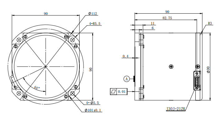
F3X90-IMU External Dimensions